I promised some (potentially amusing) examples from real life after our previous session that was focused on understanding how Wireshark presents fragmented packets. If you read part 1, then you should be prepared for what comes below. If you didn't, please go ahead and read through it, as it has quite a bit of useful information. Don't worry, I'll wait for you.
Unorderly packets
Whenever you transmit a fragmented packet you basically give up on any expectation that they will arrive in the same order at their destination. And it's perfectly OK, as the fragment reassembly process is built to work in these circumstances: you identify fragments by their ID, you use the offset field to find their place in the original packet and you keep putting pieces together until there's no other expected (MF=0). Of course, if any piece of the puzzle gets lost, the whole packet is lost.
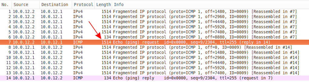
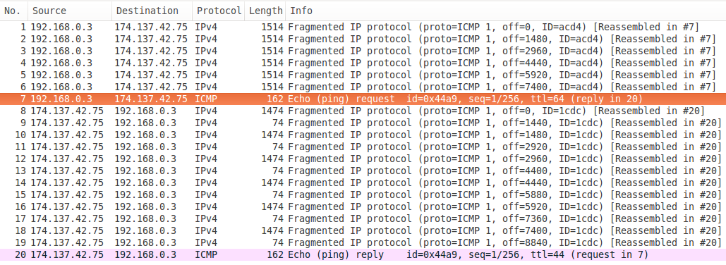
This first capture (that you can download here) looks at a simple case of the first fragment arriving last. Look above, the ICMP request is reassembled in #7, but it has a size of 1514 with the previous packet having a size of 134. Considering this filter shows only this conversation, it's clear that this is not the last fragment.
Hard to tell which one though, so for that we need to look inside. But if you look closely at the packet list you might notice there's no packet with off=0 for that ICMP request.
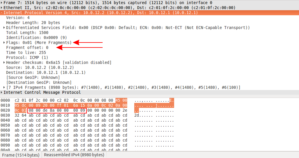
Looking at the last received fragment, be careful to select the tab that shows you only that fragment this time Frame (1514 bytes), not the whole reassembled packet. There we go, in the IP header, the offset is 0 and we're also expecting more fragments (6 more in this case).
It also contains the ICMP header that we expect to appear in the first fragment only: 08 00 de 8a 00 00 00 09.
Everything else is under control, but be prepared for those fragments to appear in pretty much any order.
Some pings in real life
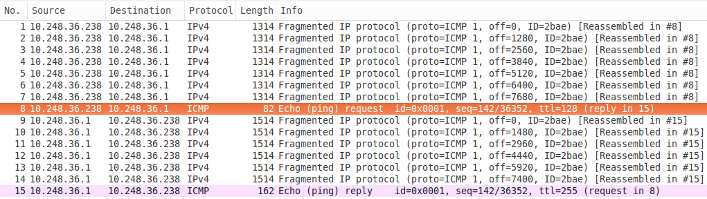
These packets are captured on a Dell laptop with Windows 8 that is pinging its gateway, a Cisco L3 switch. Notice the difference in the size of the fragments:
- the Cisco box fills up packet after packet to its maximum MTU (1518 with the Ethernet checksum that's not shown)
- the algorithm in the Windows protocol stack finds some arbitrary value of 1314 (if anyone knows where it comes from please leave a comment below) and manages to also send an extra packet because of that, taking up more space on the wire (less efficient)
OK, now let's ping from a Linux machine to a host in the Internet, over an ADSL line.
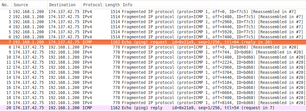
Right, that's better going out, but look at what's coming back in. That to me looks like an additional round of fragmentation taking place along the way (778+770 = 1514 + 14 + 20 so the same data plus additional L2/3 headers). Ouch.
And one more, again from a Linux machine, but over a different residential ISP connection (cable).
Interesting, isn't it? In this case the fragmenting device on the way does not cut fragments in half when it needs to, therefore giving us a better idea of what the real MTU is.
That's it
IP networks are a bit messy right now. To be more precise, IPv4 networks. I have to specify that because in IPv4 you can have fragmentation in transit, resulting in that multiple packet chopping you saw earlier.
The IPv6 specification does not allow any fragmentation on the way: only the end devices are allowed to split a packet. Of course, this has the potential for all sorts of problems when dual-stacking existing infrastructure, but the huge advantage is that it will force you to discover and fix any MTU inconsistencies you have in your network.
In conclusion, my advice is to be mindful of MTU adjustments when designing and deploying any network. Most decent devices support jumbo MTUs to allow for that extra space which can fit all the additional encapsulation those poor packets are subjected to (MPLS, VPNs, GRE, PPP etc.).
And, as always, thanks for reading.