In part 1 we had a look at some redistribution scenarios and what happens when equal-cost multi-pathing is involved.
The problem we look at in this post is what gave the series its title and it builds on the previous setup by adding VRFs and MPBGP to the mix.
The setup
I strongly suggest reading part 1 to get familiar with the setup and what's going on. What I did here is put the OSPF domain into a VRF (left) and the BGP domain into a different VRF (right). I still want communication between them, so I'm using MPBGP RT import/export on R2 to exchange routes between the two domains.
We're getting into deeper waters here, so you should have a good understanding about how MPBGP and L3VPNs work, as well as what VRF leaking is. There are lots of great articles you can read about them on the net, so I won't explain the concepts.
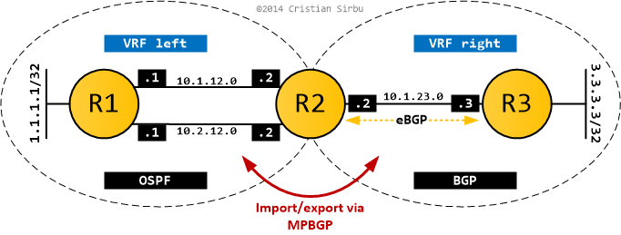
In L3VPN terms, R1 and R3 are CE routers and R2 is a PE router. The configs below show the relevant bits on R2, as this is where all the action takes place (R1,R3 configuration is trivial and doesn't change from part 1).
As you can see below, the two VRFs are configured and the RT import/export mechanism ensures that MPBGP exchanges all routes (no filtering) between the two L3VPNs.
ip vrf left
 rd 1:1
 route-target export 1:1
 route-target import 2:2
!
ip vrf right
 rd 2:2
 route-target export 2:2
 route-target import 1:1
For route exchange to actually happen, I have to redistribute between BGP and OSPF in VRF left, while VRF right enjoys the fact that it's running pure BGP and does everything transparently.
router ospf 1 vrf left
 router-id 2.2.2.2
 log-adjacency-changes
 redistribute bgp 2 subnets
!
router bgp 2
 bgp router-id 2.2.2.2
 no bgp default ipv4-unicast
 bgp log-neighbor-changes
 !
 address-family ipv4 vrf right
  neighbor 10.1.23.3 remote-as 3
  neighbor 10.1.23.3 activate
  no synchronization
 exit-address-family
 !
 address-family ipv4 vrf left
  redistribute ospf 1 vrf left match internal external 1 external 2
  no synchronization
 exit-address-family
Looking at the results
Once the bits shuffle around and the dust settles, I should be able to ping from 1.1.1.1 to 3.3.3.3. Job done. Or is it?
The expected end result should be the same as the one in Part 1/OSPF and BGP. R2 has two equal cost paths to reach R1, but only one route makes it to R3 (via redistribution).
Check the routing table output below... it looks almost right, doesn't it?
#R1
O E2    3.3.3.3 [110/1] via 10.2.12.2, 00:11:35, FastEthernet0/1
                [110/1] via 10.1.12.2, 00:11:35, FastEthernet0/0

#R3
B       1.1.1.1 [20/0] via 10.1.23.2, 00:11:54

#R2
Routing Table: left
O       1.1.1.1 [110/11] via 10.2.12.1, 00:13:20, FastEthernet0/1
                [110/11] via 10.1.12.1, 00:13:20, FastEthernet0/0
B       3.3.3.3 [20/0] via 10.1.23.3 (right), 00:12:21

Routing Table: right
B       1.1.1.1 [20/11] via 10.1.12.1 (left), 00:12:50, FastEthernet0/0
B       3.3.3.3 [20/0] via 10.1.23.3, 00:13:03
B       10.2.12.0 is directly connected, 00:12:50, FastEthernet0/1
B       10.1.12.0 is directly connected, 00:12:50, FastEthernet0/0
If you can't spot what I'm talking about (I won't blame you, took me a while to figure out), hold on for a bit, well come right back to it.
Let's walk through what happens (also with the help of the BGP tables below):
- OSPF route 1.1.1.1/32 gets redistributed into BGP from VRF
left(remember redistribution is done out of the RIB!). It might have two different next-hops, but as we've seen in part 1, it picks the numerically lowest one. - The routes that make it in BGP get tagged with RT 1:1 (the export RT for VRF
left). - Because VRF
rightimports routes with RT 1:1, 1.1.1.1/32 appears in the BGP table for VRFright, with the same next-hop of 10.1.12.1. One of your eyebrows should be gaining altitude at this point. - The routes are then advertised to R3, which is a BGP neighbor in VRF
right, and we get the routing table output you've seen above.
R2#show bgp vpnv4 unicast all
BGP table version is 12, local router ID is 2.2.2.2
Status codes: s suppressed, d damped, h history, * valid, > best, i - internal,
              r RIB-failure, S Stale
Origin codes: i - IGP, e - EGP, ? - incomplete

   Network          Next Hop            Metric LocPrf Weight Path
Route Distinguisher: 1:1 (default for vrf left)
*> 1.1.1.1/32       10.1.12.1               11         32768 ?
*> 3.3.3.3/32       10.1.23.3                0             0 3 i
*> 10.1.12.0/24     0.0.0.0                  0         32768 ?
*> 10.2.12.0/24     0.0.0.0                  0         32768 ?
Route Distinguisher: 2:2 (default for vrf right)
*> 1.1.1.1/32       10.1.12.1               11         32768 ?
*> 3.3.3.3/32       10.1.23.3                0             0 3 i
*> 10.1.12.0/24     0.0.0.0                  0         32768 ?
*> 10.2.12.0/24     0.0.0.0                  0         32768 ?
If I traceroute from R3 to 1.1.1.1/32, based on previous experience, I would expect R2 to load-balance between its two equal cost paths. But it doesn't, and in this case it's impossible to make it do so, no matter what crazy tricks you employ.
R3#trace 1.1.1.1 so lo0

Type escape sequence to abort.
Tracing the route to 1.1.1.1

  1 10.1.23.2 28 msec 32 msec 32 msec
  2 10.1.12.1 [AS 2] 56 msec 56 msec 64 msec
You were probably expecting this, but I bet there's a bit of confusion floating around as to exactly why. I gave you a few hints along the way, so lets take them in order.
VRF right shows the following route: B 1.1.1.1 [20/11] via 10.1.12.1 (left), 00:12:50, FastEthernet0/0
- what's interesting is that the next-hop is 10.1.12.1 and the outbound interface is Fa0/0 - both of which are in another VRF (
left)! - this is VRF leaking in action: traffic from VRF
rightis explicitly forced to go out of an interface in VRFleftvia a path in the routing table. This happens because there is no physical link between the two VRFs (which are like two separate routers). - the BGP table for VRF
rightshows where this came from:*> 1.1.1.1/32 10.1.12.1 11 32768 ?
VRF right shows another funny entry: B 10.1.12.0 is directly connected, 00:12:50, FastEthernet0/0
- so it's a BGP route
Bwhich isdirectly connected. Say what now? - again, it's VRF leaking in action. Fa0/0 is, indeed, directly connected to
R2. But the route has to logically pass between two VRFs and BGP was used to exchange that information.
OK, so when a packet arrives in R2-right from R3 with a destination of 1.1.1.1, the routing table instructs it so send it out via interface Fa0/0 with a next-hop of 10.1.12.1.
We can also see this in the FIB of the router:
- the CEF entry for 1.1.1.1/32 in VRF
lefthas two next-hops and two outbound interfaces, as expected - the CEF entry for 1.1.1.1/32 in VRF
righthas only one exit point, completely bypassing VRFleftRIB
R2#sh ip cef vrf left
Prefix              Next Hop             Interface
1.1.1.1/32          10.2.12.1            FastEthernet0/1
                    10.1.12.1            FastEthernet0/0
3.3.3.3/32          10.1.23.3            FastEthernet1/0

R2#sh ip cef vrf right
Prefix              Next Hop             Interface
1.1.1.1/32          10.1.12.1            FastEthernet0/0
3.3.3.3/32          10.1.23.3            FastEthernet1/0
The packet we're talking about will get chucked out of Fa0/0 directly without it actually triggering a lookup in the RIB of VRF left. And that's why there is no load-balancing.
The bottom line
So here you have it ladies and gentlemen: leaky redistribution. An ECMP route (1.1.1.1/32) gets redistributed, loses information about its equal-cost paths in the process, then VRF leaking bypasses the normal routing procedure and only uses the redistributed next-hop to forward traffic.
You might be wondering how does that apply in real-life and if it can happen to you. It can and it is quite hard to pin-point and troubleshoot as the torture you had to go through above well shows.
In today's networks it's not too difficult to have the ingredients for this to happen:
- Equal-cost paths and load-sharing PE-CE.
- Big PEs with a lot of L3VPNs on them.
- Extranetting between at least two of these L3VPNs.
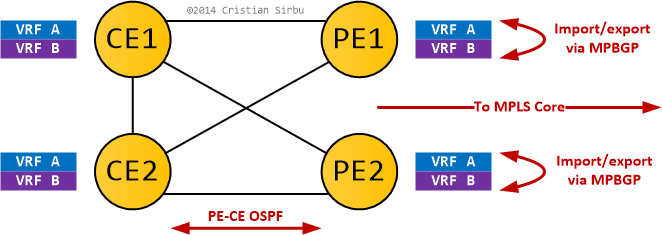
As long as the L3VPNs you do extranetting between are on different PEs, you won't feel a thing. But as soon as they reside on the same PE, those PEs will do VRF leaking (Cisco does it by default, while Juniper doesn't) and your carefully planned load-sharing might not work.
I'll leave you with the following diagram for an example where this issue happens to something that doesn't look like a lab-only topology.
And, as always, thanks for reading.